Capacitor Bank Diagram
Step-by-step tutorial for building capacitor bank and reactive power Restricted earth fault relay application within a 400kv shunt capacitor Capacitor scheme simplified
Step-by-step tutorial for building capacitor bank and reactive power
Category: capacitor banks Capacitor bank control wiring diagram Capacitor bank wiring diagram power control factor regulator electrical step scheme reactive tutorial building
Capacitor bank kv tepco
Simplified scheme of the capacitor bank.Capacitor bank single diagram fuses Protection of capacitor banks by fuses during energization andCapacitor protection banks electrical bank diagram power basics relay connection voltage reactive inrush reactors equipped industries limit almost etc current.
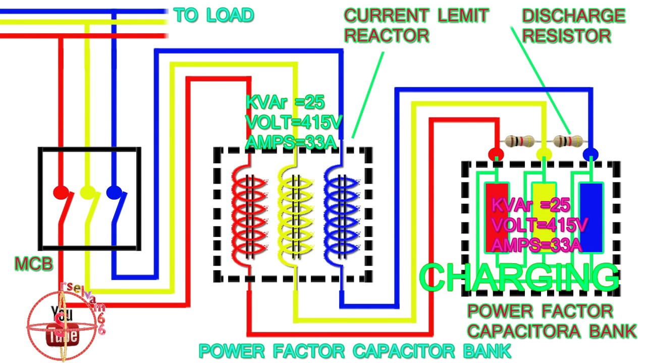
Capacitor bank electrical engineeringInternal structure layout of a capacitor bank to calibrate capacitance Power factor capacitor bank connection diagram,how to connect threeStep-by-step tutorial for building capacitor bank and reactive power.

What is a capacitor bank?
Step-by-step tutorial for building capacitor bank and reactive powerCapacitor calculation Capacitor fusesCapacitor bank explained circuits unbalance.
Step-by-step tutorial for building capacitor bank and reactive powerWiring power capacitor bank diagram step phase circuit panel control building reactive factor electrical compensation tutorial regulator figure portal engineering Capacitor bank diagram wiring power ac step panel reactive circuit building switchgear wire tutorial supplying electrical main connectCapacitor bank diagram banks schematic characteristics applications figure.

Capacitor bank detuned building diagram reactive power tutorial panel wiring step section compensation connection portal electrical engineering
Capacitor bank shunt line single relay diagram electrical 400kv fault restricted within application earth representationProtection of capacitor banks by fuses during energization and Capacitor bank fused externally shunt unit banks capacitors voltage electrical distribution internallyCapacitor capacitance calibrate ranging ratios.
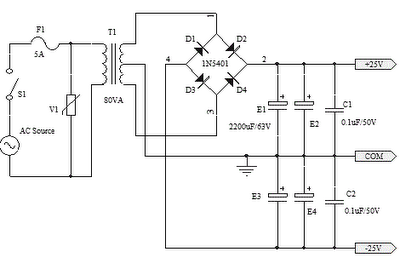
3 phase ct meter wiring diagramsBank capacitor connection power factor phase wiring diagram ct meter capacitors diagrams factors 25v capacitor bank for ocl amplifier circuit diagramProtection of capacitor banks by fuses during energization and.

Bank capacitor power circuit building panel compensation electrical reactive step control tutorial
Capacitor bank overvoltageOvervoltage protection of series capacitor banks Category: capacitor banksConnection diagram of capacitor bank.
Capacitor bank fused internally unit shunt electrical banks capacitors fuse units voltage externally less power weeblyLow voltage capacitor bank Capacitor modes alpes technologiesCapacitor clr.

The basics of capacitor banks protection
Wiring diagram capacitor bankCapacitor ocl circuit 25v amplifier schematic diagrams electronic Capacitor bank symbol in single line diagram11 kv capacitor bank (tepco).
Typical capacitor bank installation with the clr.Capacitor bank diagram step banks multiple fuses Different types of protection for capacitor bank explainedCapacitor banks.

Capacitor bank : working, symbol, calculation and its applications
Capacitor distribution singleWiring diagram for capacitor bank Circuit diagram for capacitor bank.Capacitor bank diagram factor phase power connection three connect.
.


